
I'm working on a PSK decoder that will be more resilient to fading signals and my first question is how to test it. Ideally I could use a spacecraft in orbit and record some telemetry from it, but we do not have a spacecraft in orbit with the PSK format that I am decoding. I can generate the signal in the lab but it does not have Doppler or fading. I decided to write a program that would layer the Doppler shift and fade on top of an existing signal.
The details are below. You can find the code here: https://github.com/ac2cz/SimSatellite
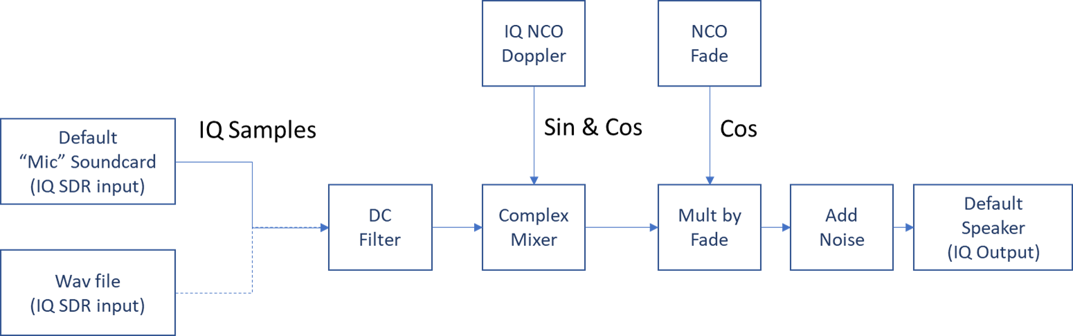
I wanted to use a live signal from a flat sat or a recording in a wave file as the source. Using an SDR like the Funcube dongle, the IQ audio is received through a soundcard. I decided to write a program that reads from a soundcard and writes to another. I could then pipe the output of the program to my decoder using a virtual audio cable.
The program is pretty simply. First, it reads from the default soundcard and writes to the default playback soundcard, so those need to be setup in the OS. This saves implementing the logic and widgets to select sound cards. I didn't add widgets for selected a wav file either, but the code is there and just needs to be uncommented.
The IQ audio is read from the source and DC filtered. This removes the central DC spike from the SDR. Without this the central spike will travel with our Doppler shift. Not what we want!
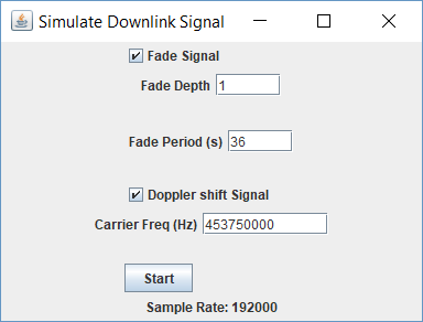
Secondly the program mixes the IQ samples with the Doppler offset frequency. So if the spacecraft is nominally on 435.750MHz and the Doppler offset is 10kHz, then it mixes the signal with 10kHz. But this is not a mix in the traditional sense, which would create a sum and difference frequency. We mix with a complex oscillator and it cleanly shifts the signal according to the Doppler with no artifacts.
Thirdly we multiply the signal by a fade amount. Usually scaling the signal by an amount has no effect because the noise and signal vary by the same amount. The Decoder then applies some gain and it looks like nothing changed. So we add a fixed amount of noise to keep the noise floor constant. Now the signal sinks into the noise as we apply the fade. Just what we want!
At first I used another oscillator to apply the fade. To avoid negative fading (whatever that would be) I shifted the cosine wave so it only had positive values from 0 - 1 and generated a raised cosine. Multiplying this by the signal applied a smooth fade with any desired frequency. To make it easy I specified the period of the fade. So putting 60 seconds simulated 1 revolution per minute. Or so I thought. This looked very impressive, but gave the decoders a lot of trouble. In this scenario the signal is missing nearly half of the time which might be realistic for a larger spacecraft where the antenna can get blocked from view, but is not realistic for a small cubesat. Our RS Forward Error Correction can not cope with it and neither the Costas Loop Decoder or the Non Coherent Dot Product Decoder can track it.
I realized with a bit of thought that it is the antenna pattern that is rotating and that the pattern is not sinusoidal. I fired up EZNEC and modeled a quarter wave antenna in free space:
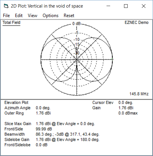
So the patter has nearly constant gain for most of the rotation with two deep nulls. Easy NEC allowed me to export the data from the plot and I loaded the values into my "Oscillator". Now instead of a cosine wave we get the antenna pattern as a fade response. We can still specify any period we want.
After more thinking I left the code in for the Cosine fade. That may more accurately represent a mismatch of polarization when the ground station has linearly polarized antenna and the spacecraft rotates so that it is cross polarized. I will need to test both situations.
I thought a simple constant change in frequency would be enough to test the Doppler. Perhaps I could model the maximum change per second and see if the decoders could hang on. That worked to an extent, but it was difficult and artificial. So instead I used the Java port of the Predict library by David Johnson G4DPZ. It did not have the Doppler calculations that I needed, so I added them. Hopefully Dave will absorb into the main library.
So now we can calculate and use the Doppler for a spacecraft. People with more knowledge than me suggested using AO-92 as a suitable model for the future orbit of Fox-1E. So I did that.
The program runs well and produces a signal shifted according to the Keps being used and fading according to the parameters specified. As well as testing the ability of the decoders to handle fading, this has now created a way for me to test better Doppler tracking in the PSK version of FoxTelem.
You can read my post about the new Dot Product decoder and its performance vs the Costas Loop.
73
Chris
g0kla/ac2Cz
Enter Comments Here:
Copyright 2001-2021 Chris Thompson
Send me an email