
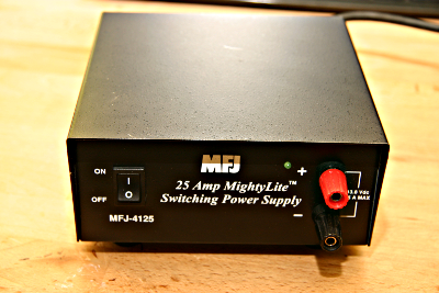
 I purchased an inexpensive switching PSU when I upgraded my K2 to the K2-100. The idea was to use the K2
and the PSU at another QTH, so it was great that the 100W station would be small and compact. The PSU works
well and is quiet in the RF bands, but it is not quiet in the audio range. The fan runs constantly at high
speed and is very noisy.
I purchased an inexpensive switching PSU when I upgraded my K2 to the K2-100. The idea was to use the K2
and the PSU at another QTH, so it was great that the 100W station would be small and compact. The PSU works
well and is quiet in the RF bands, but it is not quiet in the audio range. The fan runs constantly at high
speed and is very noisy.
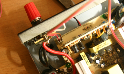
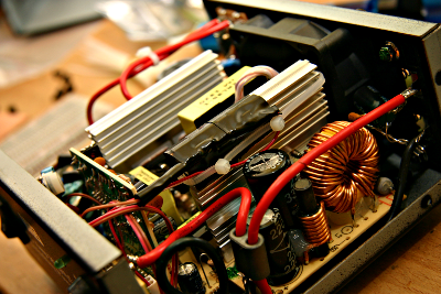
Step one was to open the PSU up and look for the fan connection. BUT FIRST A WORD OF WARNING. The heatsinks inside the power supply are live. Do not touch them or they will give you a nasty shock! No doubt many other elements inside are also dangerous. MAKE SURE YOU ARE EXPERIENCED WORKING WITH 120V EQUIPMENT BEFORE ATTEMPTING THIS MOD, OR SEEK HELP FIRST.
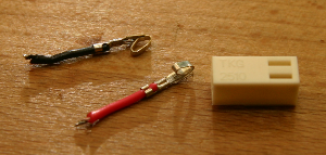
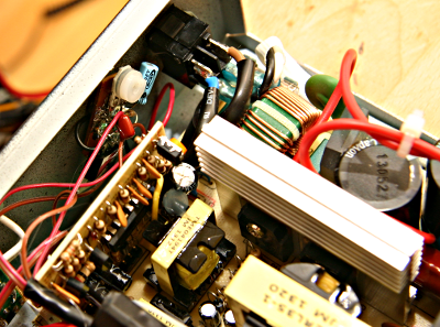
The fan connection comes underneath the board and connects at the front to a 2 pin header with red and black wires. I snipped the wires right at the connector so that the wires to the fan were as long as possible, and then removed the small pins inside the connector (with a small screw driver you can press on the tab that holds them in place). The existing wires were crimped, but I was able to carefully remove the insulation and most of the wires so that I could reuse them. I inserted my own wires into the connector. You can see the new connector plugged in below with my wires trailing out of it.
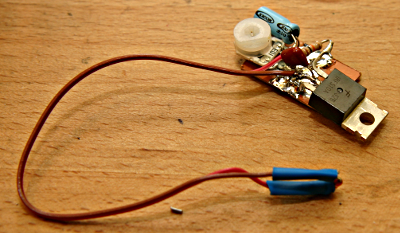
I decided to apply the same fan control circuit that I had used for my 50V homebrew PSU. This uses a thermistor to measure the temperature of the heatsink and an FET to control the fan. A variable resistor is used to set the off "temperature" for the fan. The circuit is reproduced below:
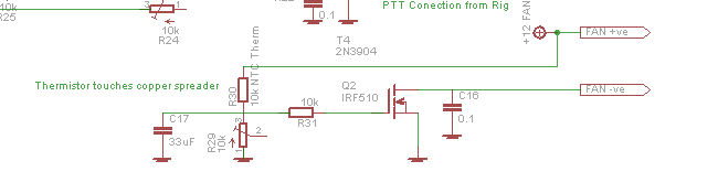
The circuit was built onto a small piece of scrap pcb, dead bug style. Not shown in the photo, I used a 1Mohm resistor as a "standoff" and attached the +ve voltage from the 2 pin header. I had forgotten which wire was positive, so I had to measure it with my multi meter. The negative wire from the header attaches to the ground of the circuit board.
The you need to take the wires that were originally cut, and which run to the fan, and attach them to the board. They are just long enough. Note that the positive red fan wire just connects to the positive voltage. The FET controls the return of the voltage to ground. So the negative, black, fan wire connects to the drain of the FET.
I plugged everything in to test it. The fan was running as normal, so I adjusted the variable resistor until it just went off. Then I found that applying heat to the thermistor by holding it or breathing on it ramped up the fan speed. SUCCESS!
The thermisor needs to be attached to the heatsink. MAKE SURE THE PSU IS UNPLUGGED. The heatsinks have a positive voltage on them. I used heat shrink tubing to insulate the wires that come up to the thermistor. I then wedged the thermistor into the heatsink, covered it in tape and then held that in place with a tie wrap.
Once the thermistor was on the heat sink I plugged the PSU back in and connected the radio. After a short while the fan was running quite fast. I adjusted the speed so that the fan was just barely turning while the radio is in receive. The fan is not audible at this speed.
I hot glued the pcb to the back of the front panel and then replaced the lid of the PSU. So far this seems to be working fine. When the radio is off the fan stops. In receive it runs at an inaudible level. With a lot of transmitting it runs faster but never seems to be as noisy as before. Let's hope I don't burn out the active devices. TRY THIS MOD AT YOUR OWN RISK!
Enter Comments Here:
Copyright 2001-2021 Chris Thompson
Send me an email