

Malpelo Island is 378km off the coast of Columbia. It's basically a barren rock that falls vertically into the sea. It counts as a separate DX entity from Columbia. Right now a brave band of people are perched somewhere on the rock and have established Amateur Radio stations on all of the major bands. That's pretty exciting.
When I heard about the DXpedition I wanted to work them. Unfortunately all of their operation is "split" meaning they transmit on one frequency and receive on another. On 40m, the only band I am QRV on, they were transmitting CW on 7024kHz and listening UP several kHz. On phone they were transmitting on 7056kHz and listening on 7170kHz. My home made radio transmits and receives on the same frequency. It's ironic, because early radios had a separate transmitter and receiver, so working split was easier. In my effort to build an integrated "transceiver" I have made working split harder.
My efforts in the CQ WW DX contest were also held back because I could not work split. Many rare DX stations transmit below 7100kHz and then listen higher up in the US phone band, sometimes above 7200kHz. It was fantastic to hear really rare stations, but very frustrating being unable to work them. So I have been meaning to modify the radio for split operation for some time. The HK0NA DXpedition spurred me into action.
I thought briefly about just using a second receiver. I have a simple superhet receiver for 40m. I would need to build an antenna switch, preferably connected to the key line. I would also have to be able to switch the headphones from one receiver to the other, because you need to be able to listen on the transmit frequency. Its critical to make sure you are in the right place in the pileup. If you are not transmitting where the DX is listening, then you don't have any chance of being heard. So I abandoned the "simple" approach of using a second receiver because it was quickly quite complicated.
Instead I decided to build a second VFO. I used the same schematic as I used for the VFO in the radio (minus the RIT circuits).
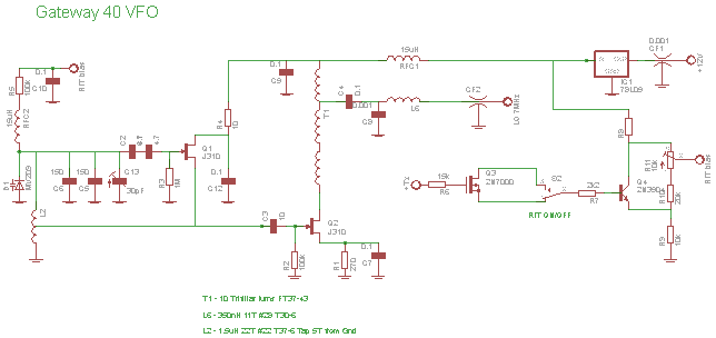
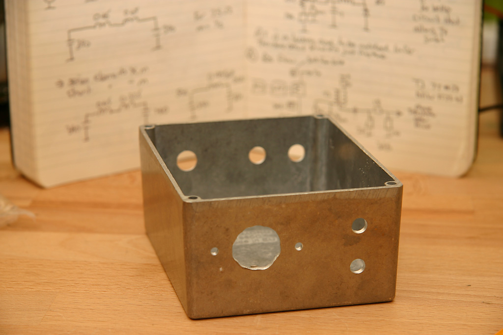
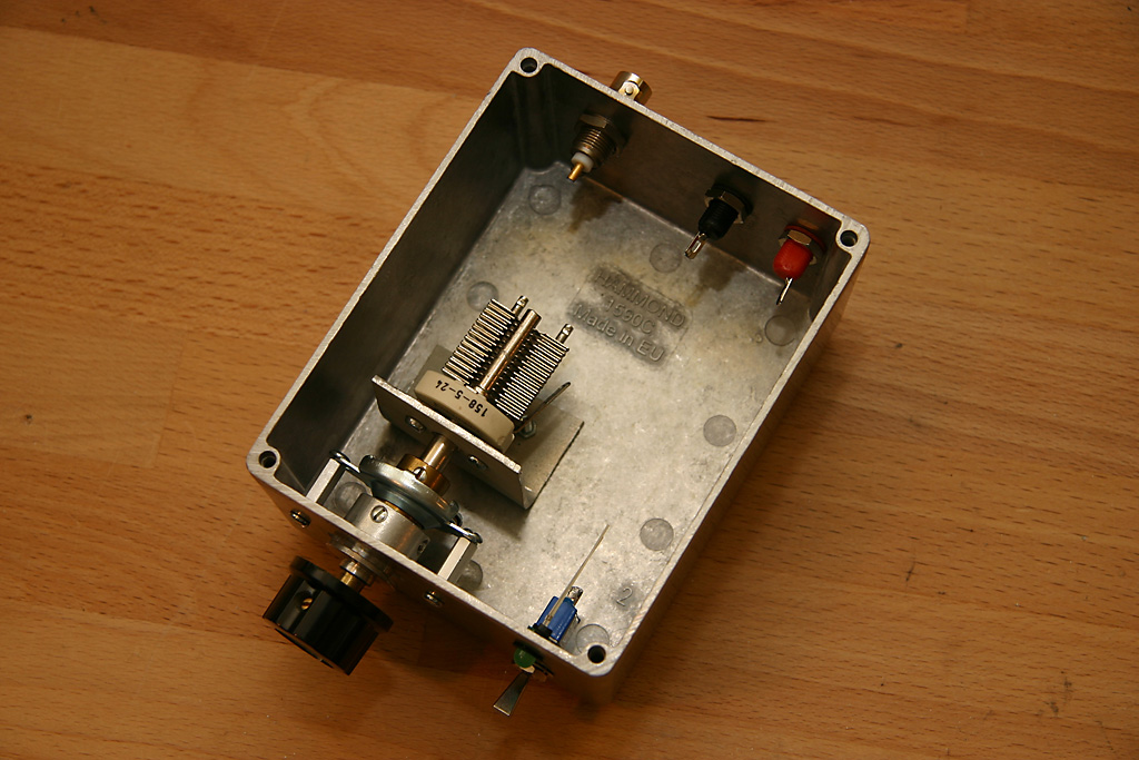
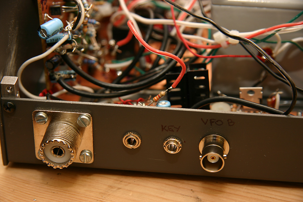
I built the VFO into a diecast box and used one of the really nice Jackson brothers 6:1/30:1 slow motion drives. I added a BNC socket to the back of the radio and I moved the "key" jack from the front panel to the back panel. That gave me a spare hole on the front panel of the radio for a toggle switch. The toggle switch is used to switch a relay, which selects the internal VFO or the external VFO as the source for the receiver. I'll label the toggle switch with "normal" and "split". When "split" is selected the relay is energized and the external VFO is used. The voltage used to energise the relay is the "receiver +Vcc". Meaning it is the supply voltage that is only active when in receive. So when the transmitter is keyed the VFO relay drops out and the radio uses the internal VFO for transmit. I thought for a while about allowing the radio to transmit on the external VFOs frequency (usually called "reverse" on radio) but decided it added a lot of complexity, would require a more stable external VFO and would not be that useful to me.
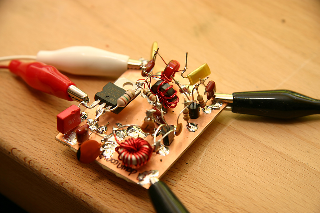
I had all the usual fun and games getting the VFO working. I used my VFO Calculation spreadsheet to get the tuning range and frequency correct. I find VFOs very frustratinig to setup without this. Once I have built the VFO I measure the frequency that it generates with the tuning capacitor at max. I plug that into the first pink cell on the spreadsheet. I plug in the values of the capacitors that I have used and it calculates an estimate for the value of the inductor. I say its an estimate because the capacitor values are approximate
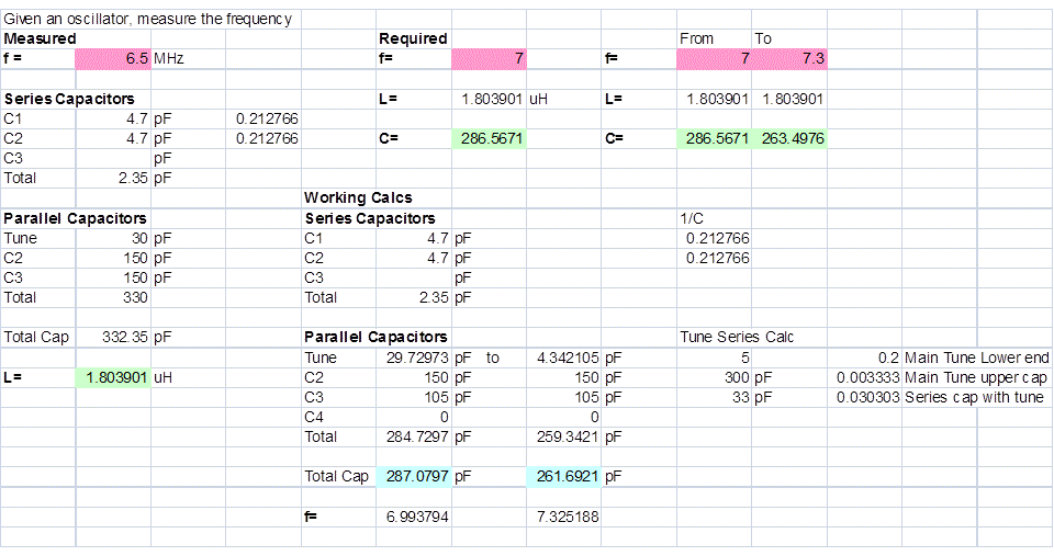 I plug the desired frequency range into the pink cells on the right hand side and it calculates the required capacitance values. I then play with the capacitor values on the right hand side, using things I have in the junk box, until I get the desired frequency range at the bottom. I usually get the tuning range right first. This is set by the capacitor that is put in series with the tuning capacitor. A small value reduces the maximum value of the tuning capacitor and reduces the range that it tunes over.
Once the tuning range is about 300kHz, I adjust the capacitors in parallel with the tuning capacitor to get the actual frequency corret. The spreadsheet gives the approximate value, then I play with 10pF capacitors until I get the value I need.
 Once the VFO was working, it was ready to test on the air. It seemed right that I should go hunting for HK0NA right away. It was 0315z and I could hear ZS3D nice and loud from South Africa. So propagation was good, at least in his direction. Maybe it was good to South America too.
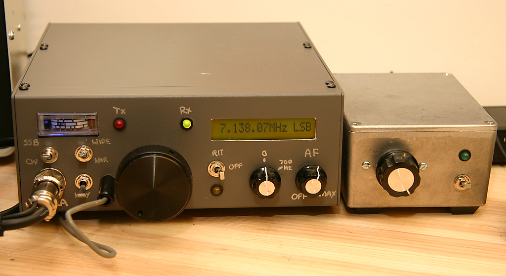
I set the toggle switch to "split" (which is still labeled "key" in the picture to the right, because that is what the old hole used to be) and started searching using the external VFO. The tuning is a bit scratchy, so I am going to need to work on that, but because it is only used for receive the quality of the external VFO is less important than the internal VFO. I checked 7056kHz but it was swamped with RTTY activity. I tuned around for a while and then found a station on 7068.27kHz with a DX accent.
This is HK0NA listening 170.

Listening 170, QRZ.
No one seemed to be calling him. I knocked over the microphone as I scrambled to bring the amplifier online. I clicked my new toggle switch to normal and raced the internal VFO up to 7170.0kHz. Thank goodness I built a frequency counter into the rig!
7170.0kHz was empty and quiet. No one was there, so I could not tell if it was exactly the frequency he was listening on. I clicked the toggle switch back to "split" and the frequency display read 7068.27kHz again.
Listening 170, QRZ.

This is Alpha Charlie Two Charlie Zulu calling you.

The station Charlie Zulu again.

Alpha Charlie Two Charlie Zulu. America Canada Two Charlie Zulu over.

Alpha Charlie Two Charlie Zulu five nine.

Roger, roger, many thanks for the five nine, you are five by five, fifty five into Brooklyn New York and my name is Chris, over.

Many thanks, please spot us on the cluster, 73.  This is HK0NA listening 170.
Wow. I don't think I have ever had a homebrew project that was such an instant success. No one else was calling him. I should have asked what the weather was like or how it was going. But I was too stunned with my success. I can recommend building a second VFO for any homebrew rig that you intend to use for working DX.
Enter Comments Here:
| On: 01/31/12 12:12Chris AC2CZ said: |
| Quick additional note. I have been toggling the normal/split switch a lot. As you are listening to a DX station you need to continually switch back to the pileup to see who is calling, are you on the right frequency, is it a good time to call now and so on. The switch should be located so that it is easy to operate repeatedly while you tuning about in the pile. Its hard to operate my switch because it is crammed in between other controls. |
| On: 04/25/16 0:00freestateQRP said: |
| Excellent informative post. Thanks for sharing your RF wisdom, Hombre! Keep up the great work! |
Copyright 2001-2021 Chris Thompson
Send me an email