
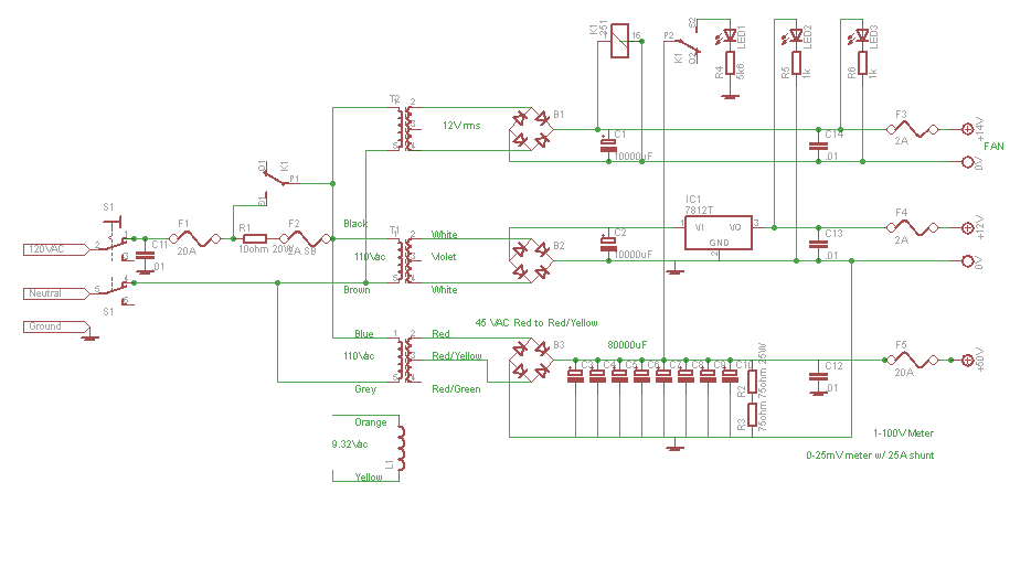
I have made decent progress on the amplifier. The Power Supply is complete and has been tested up to 15 amps at 50 volts (that was the test load that I had available). Without load it gives 60 Volts. With load this drops. The circuit is shown below:
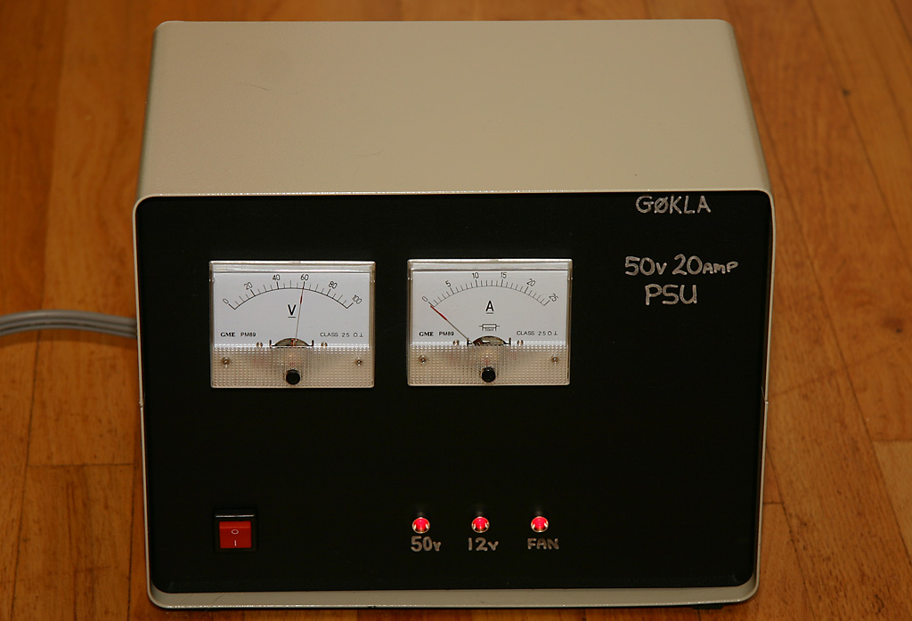
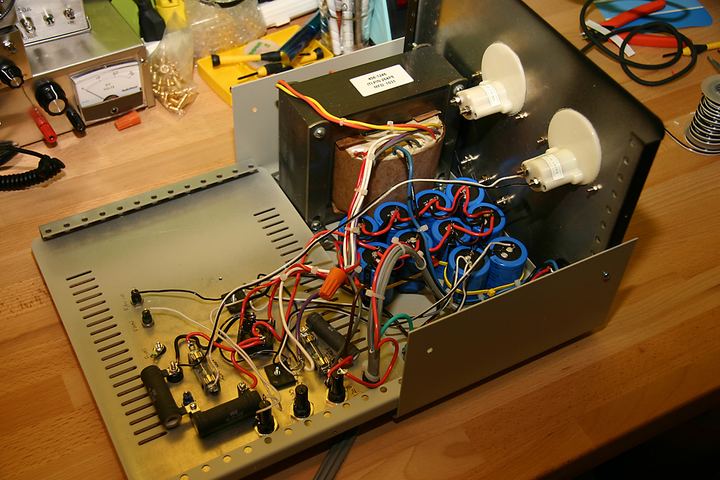
This is the finished power supply. The picture with the power supply open shows it mostly complete. It just needs the current shunt to be added for the 25 Amp meter.
Now that the PSU is complete, there are several challenges to address with the amplifier.
Drilling the copper spreader is not easy. So far I have broken two drill bits and they are buried in the holes that I am drilling. I have a drill press, but I am not used to drilling copper. Most of the time I drill aluminum. Occasionally steel.
It seems that copper is tricky. I need to use some cutting oil, go slow and make sure that the hole is cleared of debris frequently. I might also decide that 4-40 bolts are too small. The drill bit is too easy to break.
I went online to order the parts needed for the Low Pass Filters. I was surprised as the cost of Toroids (I ordered the T130 size) and
1000V Mica capacitors. At Mouser.com, some of the capacitors are $4 each, or more. I decided that 500V capacitors would be sufficient (and are half the price) based on some calculations as follows:
My assumption is that I would not run the amplifier into such a mismatched load because the transistors would be damaged before the Low Pass Filter. It has prompted me to include a forward/reflected power meter circuit as part of the amplifier, so that I can be sure that I am operating within limits. A mismatch in the opposite direction will result in high current, which could melt the relays that switch the Low Pass Filters.
Postscript:I later decided that my amplifier failure could have been because of the Ceramic capacitors that I used. I later went back to Mouser and ordered 1000V Silver Mica capacitors. I turns out that capacitor voltages need to be de-rated at RF.
I am in the dark a little about suitable relays for switching the antenna from transmit to receive, and for switching the Low Pass Filters. I have ordered some relays from allelectronics.com that are rated at 10 amps at 240 volts. That seems like a good starting point. I have no idea if they will be suitable for RF. It seems that it is relay dependant and I have to test them. That seems hit and miss. I did use one of the 10 amp relays to switch the input 120 volts around the slow start resistor in the power supply. That seems to be working fine.
For the Low Pass Filters, I have some Tyco 8 amp 250 volt relays. I have four of them. I could use them for four filters, given each have two poles, or I could parallel the poles so that they handle more current. A 1:2 mismatch to a 25 ohm load gives 6.9 amps rms, or 9.7 amps peak. So I think it is prudent to use one relay at either end with the poles connected in parallel. Voltage may be the issue here though. I do not know if the relays will withstand 3 or 4 hundred volt peaks.
Enter Comments Here:
| On: 11/30/24 6:06 Arthur Smith said: |
The power dissipation of the bleeders can be reduced by increasing their resistance. The trade off is that the bleed time will increase, which is only a concern if you intend to do servicing immediately after switching off the power. Using 500 Ohms total, for example, will produce only 5 Watts of dissipation, but the bleed time-constant will be extended from 12 seconds to 40 seconds. Keep this in mind when servicing to be sure the capacitor bank has discharged. In normal use there is no need for a fast bleeder because you will not be opening the cover. The fast bleeder comes from safety regulations applying to commercially made equipment. |
| On: 11/30/24 9:09 Chris g0kla said: |
Thanks Arthur, that is a great comment. |
Copyright 2001-2021 Chris Thompson
Send me an email