
The files for this tutorial are available on github.com/ac2cz/SDR - don't cut/paste the code from this tutorial without reading to the end, because there are bugs that must be fixed. The code on github does not contain the bugs.
Our adventures in Software Defined Radio have allowed us to play with a relatively narrow band device at 192,000 samples per second. Many SDRs can grab 2 or even 6 MHz of spectrum. If we apply the techniques we have learned so far then our code will grind to a complete stop. How do you pull out and decode a narrow band signal from 2MHz of spectrum without that happening? The trick is in the filtering. Our approach to down-convert a target signal to 0Hz and then decimate is a good one. But the filters we are using will be too slow. We need much faster filters that somehow have the same performance. So on that note, let's design and build a digital polyphase filter that we can use for efficient decimation. We will start from our old friend the FIR filter.
Remember the FIR filter, which performs a multiply and accumulate on every sample? You may remember from previous tutorials that the code looks like this:
	public double filter(double in) {
		double sum;
		for (int i = 0; i < M; i++)
			xv[i] = xv[i+1];
		xv[M] = in;
		sum = 0.0;
		for (i = 0; i <= M; i++) {
			sum += (coeffs[i] * xv[i]);
			totalCalcs++;
		}
		return sum;
	}
Previously we used a fixed set of coefficients for the filters that we calculated in another program. That works, but it can limit us when we change the bandwidth or cutoff frequency. So here is a new method that we can call from our FirFilter class which builds the coefficients. Specifically this will build a Raised Cosine shaped filter. I put it in a class called Filter in the Signal package. In the future we can put other filter kernels here. We pass it the sampleRate, the cut off frequency, something called alpha which sets how sharp the roll off is (which other references call beta) and the length of the filter. It calculates each of the coefficients, taking into consideration two special cases - the center of the filter and when we can have a divide by zero. It also calculates the sum of the squares of the coefficients. This is used to normalize the coefficients so that the filter has a total gain of 1. You can find this formulae and others in good DSP text books. The value of alpha can be set to 0.5 initially.
public class Filter {

	public static double[] initRaiseCosine(double sampleRate, double freq, double alpha, int len) {
		int M = len-1;
		double[] coeffs = new double[len];
		double Fc = freq/sampleRate;

		double sumofsquares = 0;
		double[] tempCoeffs = new double[len];
		int limit = (int)(0.5 / (alpha * Fc));
		for (int i=0; i <= M; i++) {
			double sinc = (Math.sin(2 * Math.PI * Fc * (i - M/2)))/ (i - M/2);
			double cos = Math.cos(alpha * Math.PI * Fc * (i - M/2)) / ( 1 - (Math.pow((2 * alpha * Fc * (i - M/2)),2)));

			if (i == M/2) {
				tempCoeffs[i] = 2 * Math.PI * Fc * cos;
			} else {
				tempCoeffs[i] = sinc * cos;
			}

			// Care because ( 1 - ( 2 * Math.pow((alpha * Fc * (i - M/2)),2))) is zero for
			if ((i-M/2) == limit || (i-M/2) == -limit) {
				tempCoeffs[i] = 0.25 * Math.PI * sinc;
			}

			sumofsquares += tempCoeffs[i]*tempCoeffs[i];
		}
		double gain = Math.sqrt(sumofsquares);
		for (int i=0; i < tempCoeffs.length; i++) {
			coeffs[i] = tempCoeffs[tempCoeffs.length-i-1]/gain;
			//System.out.println(coeffs[i]);
		}
		return coeffs;
	}
}
We can call this from the constructor in our FirFilter class if we want. Or better, we can pass the coefficients to the FirFilter. Here is an example constructor that will do that.
	public FirFilter (double[] taps) {
		coeffs = taps;
		M = coeffs.length-1;
		xv = new double[M+1];
	}
Let's test this before proceeding. We are going to use this as the base for our (more complex) polyphase filter, so it has to work. We can create a simple main function to pop up a window that plots a signal before and after filtering, together with a main method that calls it. LineChart is unchanged from early tutorials, except I added a line to print the title of the chart.
public class MainWindow extends JFrame {

	LineChart lineChart;
	LineChart lineChart2;

	public MainWindow(String title) {
		super(title);
		this.setDefaultCloseOperation(EXIT_ON_CLOSE);
		setBounds(100, 100, 740, 600);
		setLayout(new BorderLayout());
		lineChart = new LineChart("Source");
		lineChart2 = new LineChart("FIR");
		add(lineChart, BorderLayout.NORTH);
		add(lineChart2, BorderLayout.CENTER);
		lineChart.setPreferredSize(new Dimension(100, 200));
	}

	public void setData(double[] data) {
		lineChart.setData(data);
	}
	public void setData2(double[] data) {
		lineChart2.setData(data);
	}
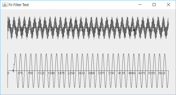
Here is a simple main method that calls it. All of this should be familiar from earlier tutorials. We create two signals, one at 1kHz and another at 8kHz. We create a filter at 6kHz. We run the filter against the data and display the two waveforms on the main window.
public static void main(String[] args) {
	int fs = 192000;

	Oscillator osc = new Oscillator(fs, 1000); // Signal we want to recover
	Oscillator osc2 = new Oscillator(fs, 8000); // noise in the channel
	MainWindow window = new MainWindow("Fir Filter Test");
	FirFilter firFilter = new FirFilter(Filter.makeRaiseCosine(fs, 6000, 0.5, 480));

	int len = 6000;

	double[] buffer = new double[len];
	double[] buffer2 = new double[len];

	for (int n=0; n< len; n++) {
		// Fill buffer with the test signal
		double value = osc.nextSample();
		double value2 = osc2.nextSample();
		buffer[n] = value + value2;

		// Filter
		buffer2[n] = firFilter.filter(buffer[n]);
	}

	// Show the waveform
	window.setData(buffer);
	window.setData2(buffer2);

	window.setVisible(true);

	}
}
And it looks pretty good. We can see the combined waveforms in the top plot and the clean recovery of the 1kHz wave in the bottom.
Finite Impulse Response Filters are great. They are easy to understand and linear phase if they are symmetrical. But they are slow. They need a lot of calculations if the filter has a sharp response. When we decimate from a wide bandwidth to a narrow one we must low pass filter to avoid aliased signals in the down sampled data (more on that as we build and test an example filter). The filtering happens at the full bandwidth of the SDR. With all the multiplies and adds needed for the convolution calculation, the FIR filter is usually too inefficient.
You might think that we can just run an FIR filter on the values that we want to keep after decimation, but you would be wrong. Decimation is not time invariant. That is a fancy term which means that we can't swap the order of the decimation and the filtering in the same way we can swap many other DSP activities. So we have to filter first at the higher data rate. Intuitively that feels right because the filtering is required to remove frequencies that will alias once we reduce the sample rate. If we reduce the sample rate first then the aliased signals are mixed into our result and impossible to remove. So we must filter at the high data rate, which means a lot of calculations.
The theory of polyphase filters is covered in major text books, such as Understanding Digital Signal Processing by Richard Lyons, Section 10.7. We start with the coefficients for an FIR Filter. We divide them into N sets of coefficients, where N is the decimation amount. So the number of taps must be divisible by N. We use these sets of coefficients to create N sub-filters. When we apply the data to the sub-filters, and switch between them in a clever arrangement, it means no unnecessary computations are performed and yet we get exactly the same result as the original FIR filter. For a decimation by 10 we perform only about a tenth of the calculations.
The approach is shown below for a polyphase filter decimating by a factor of 4. Inputs arrive at the pre-decimation sample rate. Once we have accumulated 4 we can apply them to the sub-filters and sum the results. This produces one output. Each sub-filter looks just like an ordinary FIR filter. They each have one quarter of the taps arranged so that only the required calculations are made. Otherwise they take inputs into their delay line and perform multiply/accumulate operations like any other FIR filter.
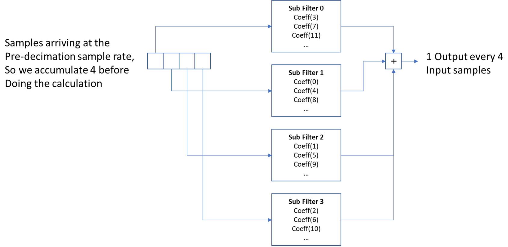
This looks complex, so we have to be careful as we lay out the code.
We can implement the polyphase filter in a new class that is going to be very similar to the FirFilter but it will use an array of the existing FirFilters for the sub filters. It calls the makeRaisedCosine() method to create the taps. The sub-filters must filter all signals less than the original sampleRate divided by two and divided by the decimation rate. Given our Raised Cosine as an alpha of 0.5, our rolloff is 50% of the bandwidth. So we must allow for that rolloff when we set the cutoff frequency, to ensure that the stop band is tight enough.
With the taps created we then use a new method, initSubFilters(), to allocate the taps to the sub filters.
	double alpha = 0.5;
	FirFilter[] subFilters;

	public PolyPhaseFilter(double sampleRate, double freq, int decimationRate, int len) {
		R = decimationRate;
		coeffs = Filter.makeRaiseCosine(sampleRate, freq, alpha, len);
		System.out.println("Raised Cosine PolyPhase Filter");
		initSubFilters();
	}

	private void initSubFilters() {
		M = xcoeffs.length-1;
		subFilters = new FirFilter[R];
		int P = R - 1; // position of the polyphase switch

		for (int j=0; j < R; j ++) {
			double[] taps = new double[M/R];
			for (int i = 0; i < M/R; i++) {
				taps[i] = (xcoeffs[P + i*R]);
				System.out.print("Tap: " + (P + i*R) + " ");
			}
			subFilters[j] = new FirFilter(taps);
			System.out.println("");
			P = P - 1;
			if (P < 0)
				P = R - 1;
		}
	}
Calling the sub filters is then relatively easy, but it needs some thought as we need to accumulate enough samples to produce a single output. So we write a function to take an array of samples and process them through the sub filters:
	public double filter(double[] in) {
		double sum;
		int i;
		sum = 0.0;
		for (i = 0; i < in.length; i++)
			sum += subFilters[i].filter(in[i]);
		return sum;
	}
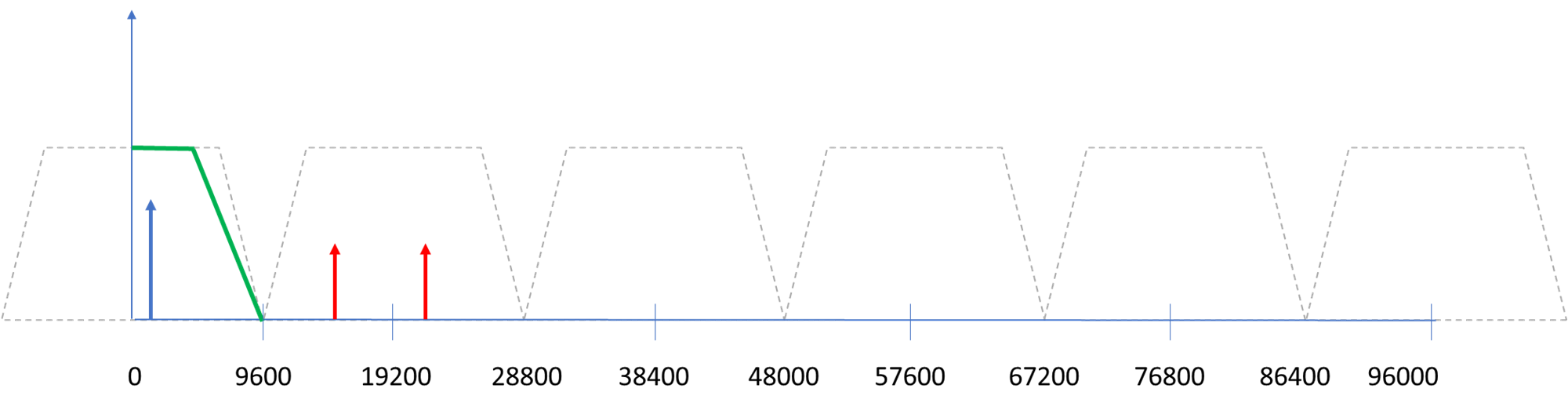
To test we will use 192,000 samples per second and then decimate by a factor of 10 to give us a bandwidth of 19.2kHz. This means we want to filter out all frequencies above 9.6kHz. But what test signals should we inject to prove this is working? The spectrum below tries to show what is going on. We show the available spectrum for 192,000 samples per second, that is from 0 to 96,000Hz. We don't have any negative frequencies because this is a real signal and not a complex IQ signal. An actual implementation would use I and Q requiring two filters, but the theory is all the same, so we will test this with a real signal.
The bold blue arrow represents the signal that we want to recover. It is a 1kHz tone but it might have been a DX CW signal or a digital transmission somewhere in our bandwidth, which we have down-converted to be at 1kHz, ready for demodulation.
When we decimate by 10 our sample rate is then 19,200 samples per second and we can have signals from 0 - 9,600Hz without aliasing. The trapezium to the left that appears to extend from -9600 to +9600 represents the bandwidth after decimation. But everything is relative in Digital Signal Processing, so all of the other trapeziums to the right are spectral replications of our bandwidth. One way to think about decimation is like sampling real world analog signals. If we sampled some real world signals at 19,200 samples per second, and there was a real world signal at 10,000Hz, then we know that would cause us an issue because it is greater than 9,600Hz. Decimation works the same except in this case we are sampling a 192,000 samples per second signal rather than a real world one. When we decimate we can imagine all of the replicated spectrum to the right of 9,600 collapsing down and being superimposed on top of our target spectrum. This is why we need to filter things out first.
So we add a test signal at about 10,000Hz, shown in red, and another at 19,500Hz, which will produce an aliases signal at about 300Hz if not filtered out correctly.
Now we need a new or modified main() method to test that this works. We add another "trace" with a LineChart so that we can see the polyphase filter along side the FirFilter. As expected the FirFilter needs to be run on every sample but the polyphase filter only runs each time we decimate, but it takes all of the samples as input.
	public static void main(String[] args) {
		int fs = 192000;
		int R = 10;
		int len = 6000;
		int decimateCount = 0;

		Oscillator osc = new Oscillator(fs, 1000); // Signal we want to recover
		Oscillator osc2 = new Oscillator(fs, 8000); // noise in the channel above the decimated freq - alias issue
		Oscillator osc3 = new Oscillator(fs, 18000); // frequency that will alias
		MainWindow window = new MainWindow("PolyPhase Filter Test");

		PolyPhaseFilter polyPhaseFilter = new PolyPhaseFilter(fs, 1500, R, R*48);
		FirFilter firFilter = new FirFilter(fs, 4500, R*48);

		double[] buffer = new double[len];
		double[] buffer2 = new double[len/R];

		double[] in = new double[R];

		for (int n=0; n< len; n++) {
			// Fill buffer with the test signal
			double value = osc.nextSample();
			double value2 = osc2.nextSample();
			double value3 = osc3.nextSample();
			buffer[n] = value + value2 + value3;

			//		double filtered = firFilter.filter(buffer[n]);
			in[decimateCount] = buffer[n];
			decimateCount++;
			if (decimateCount == R-1) {
				decimateCount = 0;
				buffer2[n/R] = polyPhaseFilter.filter(in);
				//			buffer2[n/R] = filtered;
			}
		}

		// Show the waveform
		window.setData(buffer);
		window.setData2(buffer2);

		window.setVisible(true);

	}
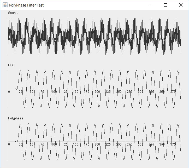
We run the the test and the results are not great. In fact it looks like the test signal 3 is leaking through and is visible in our result. The effect is a lower frequency wave modulating our 1kHz wave.
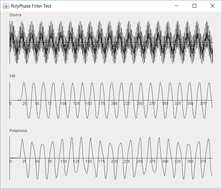
I didn't add this bug for effect. This is really in my code somewhere. If we were testing this with live data the signal might sound a bit distorted but it would appear to work, so this emphasizes the need for an experimental method where we test small units of the SDR in isolation. Fixing this bug is going to be hard, but it would be impossible in a broader program.
To narrow down the problem we need to reduce the amount of data so we can inspect the code with the debugger. I shortened the filters to just 12 taps and then started to step through the code with the debugger. As I stepped through the main() inspecting the values processed by the filters I quickly saw an error. The code is incrementing the decimation count before doing the decimation. It should be after. Right now only 3 sample values are sent to the polyphase flter. This is the loop code currently:
		double filtered = firFilter.filter(buffer[n]);
		in[decimateCount] = buffer[n];
		decimateCount++;
		if (decimateCount == R-1) {
			decimateCount = 0;
			buffer2[n/R] = filtered;
			buffer3[n/R] = polyPhaseFilter.filter(in);
		}
And this is what it should be:
		double filtered = firFilter.filter(buffer[n]);
		in[decimateCount++] = buffer[n];
		if (decimateCount == R) {
			decimateCount = 0;
			buffer2[n/R] = filtered;
			buffer3[n/R] = polyPhaseFilter.filter(in);
		}
Running the test again with the full filter lengths gives us a much better looking result:
But let's try some more values. It needs to work across the spectrum. What if we plug in 19,000 for test signal 3. That is very close to our sample rate. Uh, oh. That looks like it breaks things:
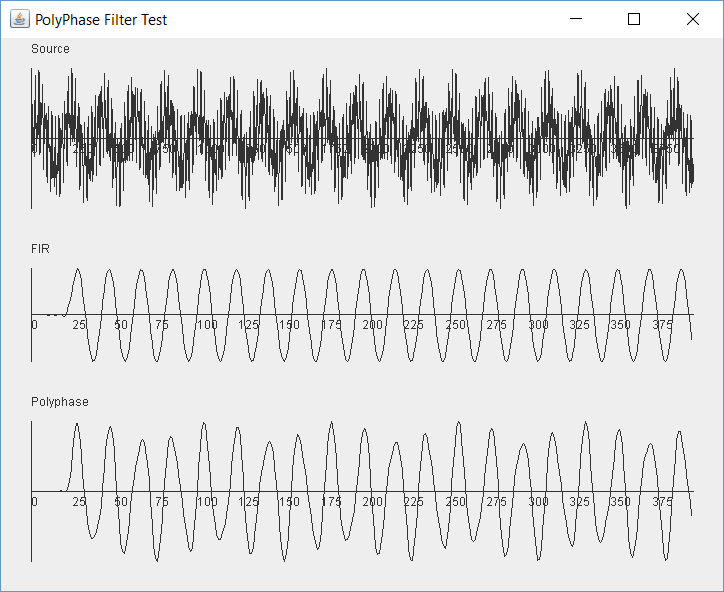
It seems that the 19,000Hz signal alias is not filtered out by the polyphase filter. The Fir Filter is working fine. The polyphase filter should produce exactly the same result even though it uses a 10th of the calculations, so this is another bug...
This is a harder one. Stepping through the code as before with short filters produces no joy. There is a bewildering set of numbers that sroll through the filters. All the buffers and arrays seem to fill correctly, so where do we go next?
I wrote a new filter generation method to produce test values. Now the coefficients will be a set of integers.
		public static double[] initTest(double sampleRate, double freq, double alpha, int len) {
		int M = len-1;
		double[] coeffs = new double[M+1];
		for (int i=0; i < len; i++)
			coeffs[i] = i+1;
		return coeffs;
	}
I then added some print statements to show the calculation results. For example the FirFilter filter() method was "instrumented" like this:
		public double filter(double in) {
		double sum;
		int i;
		for (i = 0; i < M; i++)
			xv[i] = xv[i+1];
		xv[M] = in;
		sum = 0.0;
		for (i = 0; i <= M; i++) {
			sum += (coeffs[i] * xv[i]);
			System.out.println(coeffs[i] + " * " + xv[i]);
		}
		System.out.println("Sum: " + sum);
		return sum;
	}
Now we will be able to see what get's calculated and what the sum is. This will be printed when we run the FirFilter and for each of the sub-filters in the polyphase filter. I also added a print statement in the filter() method of the polyphase fitler to show the sum across the subfilters.
To further simplify I set the sample rate to 48 and only used one test signal at 10Hz. With filters length 12 I set the length of the test (len) to just 24. So we will get a very short set of results. I stepped through the code to obtain the first few samples, running it for the FirFilter alone and then the polyphase filter alone, saving off the results for each run.
| polyphase | FIR |
|---|---|
Sample 3 4.0 * 0.0 8.0 * 0.0 12.0 * 0.9569403357322089 Sum: 11.483284028786507 3.0 * 0.0 7.0 * 0.0 11.0 * 0.5141027441932218 Sum: 5.655130186125439 2.0 * 0.0 6.0 * 0.0 10.0 * -0.7071067811865475 Sum: -7.071067811865475 1.0 * 0.0 5.0 * 0.0 9.0 * -0.881921264348355 Sum: -7.937291379135195 PF Sum: 2.130055023911276 |
Sample 3 1.0 * 0.0 2.0 * 0.0 3.0 * 0.0 4.0 * 0.0 5.0 * 0.0 6.0 * 0.0 7.0 * 0.0 8.0 * 0.0 9.0 * 0.9569403357322089 10.0 * 0.5141027441932218 11.0 * -0.7071067811865475 12.0 * -0.881921264348355 Sum: -4.607739301710184 |
Looking through the results carefully we see that our FIR has the first four values multiplied by coefficients 9,10,11,12. e.g., 0.9569 is applied to tap 9. But for our polyphase filter it is applied to Tap 12. Similarly 0.514 is multiplied by tap 10 but for our polyphase it is multiplied by Tap 11.
So we appear to have the calculations in the opposite order. Are the taps wrong, or is it how we call the calculations?
Our decimateCount runs from 0 - R-1 e.g. 0-3 for decimation by 4. We add the data into the in[] array sequentially. Once it is full we call the PolyPhase filter. We then put one value in each sub filter, which runs the calculation
So this suggests that the subfilters are in the wrong order. One easy test is to change the order that the data is applied to them, as shown below.
		public double filter(double[] in) {
		double sum;
		int j = in.length-1;
		sum = 0.0;
		for (int i = 0; i < in.length; i++)
			sum += subFilters[i].filter(in[j--]);
	//		sum += subFilters[i].filter(in[i]);
		System.out.println("Sum: " + sum);
		return sum;
	}
Rerunning the test above shows that the multiplications are now identical. So we comment out the print statements and reset the test to be 192,000 samples per second with full filter lengths and the three test signals. Don't forget to change back the filter taps from the test set to the real set. Or try running it with the test set. I did by accident and it almost works... Which shows why this stuff is so tricky to get right.
But with the right filter coefficients we get this:
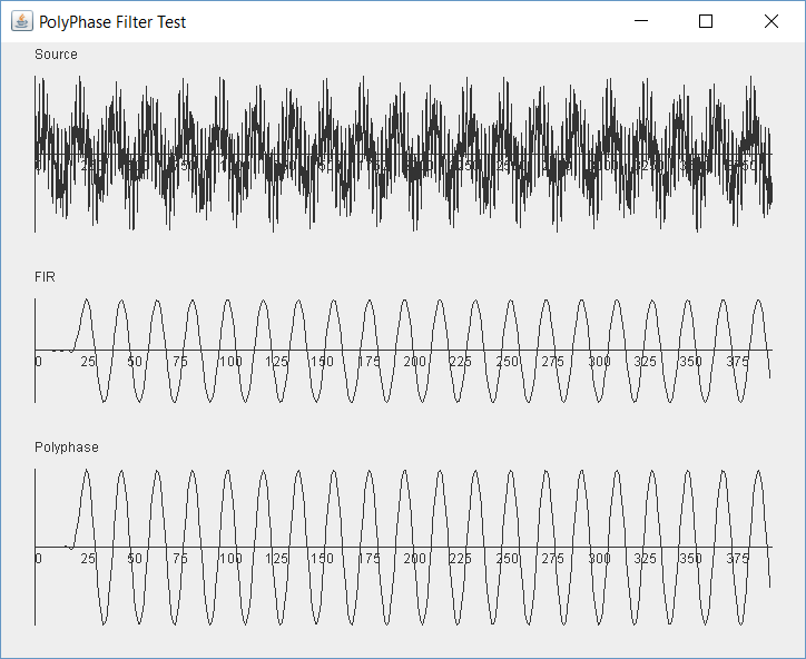
Which looks excellent. Feel free to try all sorts of values that might break it. In every case the FIR and polyphase results should be the same.
We now have solid tested code that decimates at high rates and uses a fraction of the calculations needed by a classic FIR filter, yet we get the same result. This will be very useful when we want to decimate by large amounts.
One futher note before we finish this tutorial. It is common to decimate by quite large amounts. For example if we have an SDR with 960kHz of bandwidth and we want to decimate to a 48kHz channel, then the decimation factor is 20. If we want to take 2.4GHz of bandwidth down to 9,600Hz then the decimation is 250. The FIR filter to seperate out such a narrow slice needs to be incrediblly sharp and the process breaks down even if we use a polyphase filter. Instead we decimate in two or more stages. So perhaps 2 and 10 to get 20? Or 4 and 5? In fact there is a formula that tells us the best two stage decimation factors L1 and L2, worked out by the wizards of DSP yore:
F = (fstop - B) / fstop
L2 = 2L * ( (1 - Sqrt ( LF / (2 - F))) / ( 2 - F * (L + 1)) )
L1 = L / L2
Prev Tutorial | Index | Next Tutorial
Enter Comments Here:
Copyright 2001-2021 Chris Thompson
Send me an email