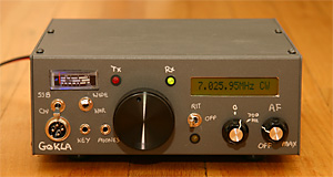

I built this radio when I got back on the air after a break away from the hobby. It is based on the R2 Receiver and T2 Transmitter by KK7B that are described in the 2009 ARRL handbook. There are several versions of these "modules" and they are more fully described in Experimental Methods in RF Design (EMRFD), the Amateur Radio constructors bible. The modules themselves went together fairly easily. The challenge was testing them when I did not have another radio. I also spent quite a lot of effort integrating them into a transceiver.
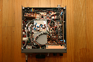
I constructed the whole radio ugly style, except for the digital display, which is a kit from Almost All Digital Electronics. In picture below the VFO is inside the grey die cast box in the middle. A Jackson Brothers reduction drive couples the VFO to the knob on the front panel. The radio is built inside the box for the Electraft K2, which they sell separately for this type of construction project.
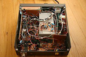
Under the Lid - Top View
 To the left of the VFO is the transmitter, on two boards. One for the RF and one for the audio phasing that eliminates the sideband.
One of the boards it mounted vertically on the side panel and the other is mounted on the bottom of the box.
To the right of the VFO is the receiver, also on two boards, again with one of them mounted vertically on the side panel. There is also a board for the tx/rx control and a small board hidden at the back with the low pass filter.
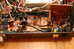
The PA modules are across the back of the box. The PA module to the left takes the 0dBm signal from the transmitter and amplifies it to 0.5 Watts. The IRF510 PA to the right produces 5 Watts from a 12 Volt supply and up to 10 Watts from 18 Volts.
On top of the VFO is a newly built board that I have not mounted yet. It samples the received audio and drives the S-meter.
The digital frequency display is sealed in a box made from PCB material, in the bottom right of the picture. For a long time I struggled to remove the clock noise from this circuit until I realized that moving the radio further away from the antenna worked. The noise was coming out of the front of the display and being picked up by the antenna.
The R2 and T2 circuits are widely available online, in EMRFD and in the ARRL Handbooks. I followed them pretty closely, making adjustments to incorporate a stable VFO (not the one in the R2 design). Much of the control circuitry and the PA modules were inspired by EMRFD. I'll post the circuits here when I get a chance. If anyone is interested in them, then please email me.
Rear View and a more detailed picture of the 0.5W and 5W PA boards


This radio works pretty well and I have had a lot of fun with it. I have built a simple 50W PA and have worked several stations in Latin America and Europe, as well as stations all over the US and Canada. Signal reports are good. The opposite sideband seems to be well suppressed and people can not hear it.
There are some problems that I hope to address in a new radio I am designing (such as temperature compensation for the VFO), but they are minor compared to the joy I have had operating this homebrew radio.
Copyright 2001-2021 Chris Thompson
Send me an email