
I wrestled with the amplifier over several evenings and for most of Saturday morning. The control board did not work when I installed it in the amplifier. The current sense would trip and the reset switch did not seem to clear it. Sometimes it would work, sometimes I would need to turn the trip current value right up, just to get it to reset, then I could set it back to the right value. It was very frustrating. Applying the 50V supply to the sense resistor seemed to stabilize the current sense reset, but my issues were not over.
Next I noticed that the TxRx relay was not switching over reliably. It turned out that the supply voltage for the control circuits was only 11.8 volts. Once it had gone through the TIP29A and the 2N3906 it had lost 1.5 volts. That was not enough to power the relay. It turned out that it was also not enough voltage to reliably reset the 4044. I used a separate 13.8 volt supply temporarily and everything worked. So I will need to update the power supply to deliver 13.8 volts or 14 volts rather than 12 volts. I will also add a small separate transformer for the fan so that it is not pulling down the 14 volt supply.
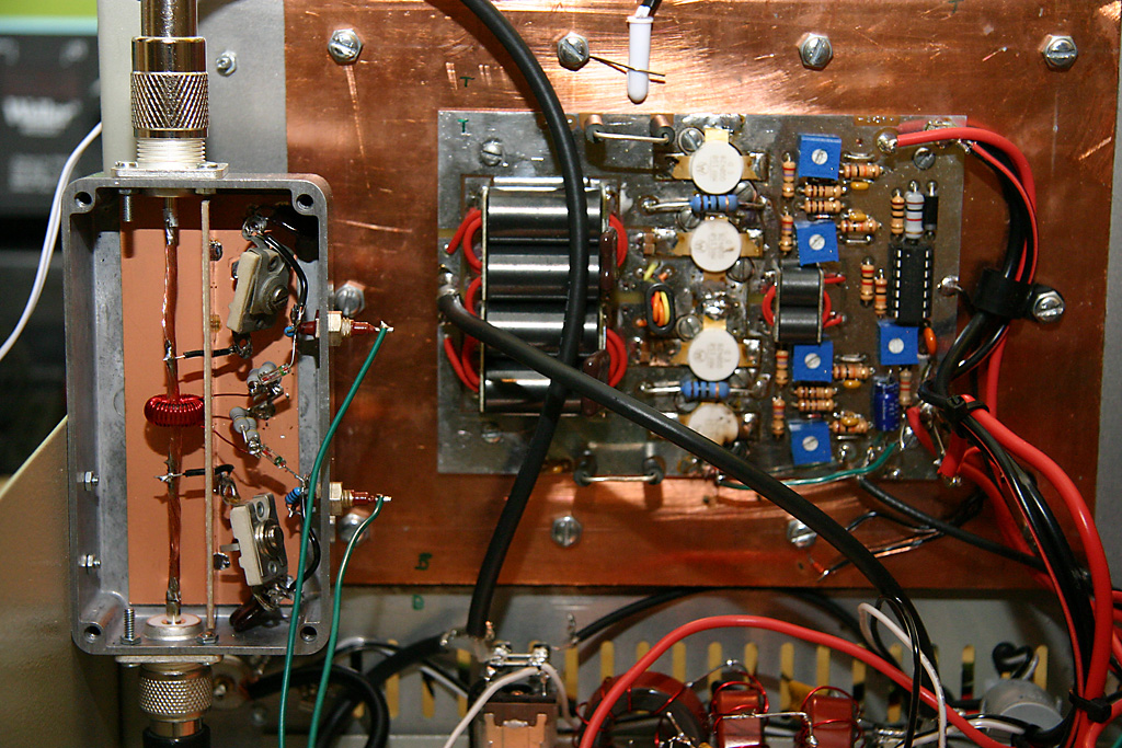
I built the SWR sensor based on the August 1983 QST Article "A beginners look at RF Power Measurement" by Doug Demaw W1FB. It's a classic circuit, first described in the December 1969 QST Article "In-line RF Power Metering" also by Demaw. I built the circuit in a small diecast box with SO-239 connectors at either end and feed-through capacitors for the sense voltages. I used germanium diodes, not sure which type. I put a piece of PCB down the center of the diecast box to separate the transmission line from the sense circuits. Mica compression trimmers were used to balance forward and reflected power readings. I had all of these components in the junk box luckily. Below is a picture of the thru-line power meter with the cover removed and a picture that shows how it is mounted in the amplifier.
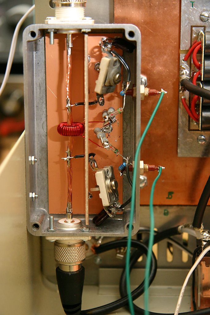
Testing was not that hard once I realized that the metal lid needed to be in place for each test (otherwise any adjustments are useless once the lid is replaced). I measured the current directly with a DVM and disconnected the potentiometers and the panel meters. The reflected power null current was about 5-6 uAmps. The only problems found were accidental short circuits between the trimmer capacitors and ground. I used my 50 watt PA to run power in each direction through the sensor and then to set the level of the reflected power trip on the control board. I set it so that it will trip with 30 Watts of reflected power.
I installed the new transistors and again setup the bias current to 250mA per device. I ran a series of tests starting with low power and building up. Results are as follows:
| Input(W) | Output(W) | Supply(V) | Current(A) | Power In(W) | Efficiency(%) |
| 1 | 150 | 50 | 9.5 | 475 | 32 |
| 2 | 200 | 48 | 12 | 576 | 35 |
| 3 | 300 | 47 | 14 | 705 | 43 |
| 4 | 350 | 46 | 16 | 736 | 48 |
| 5 | 400 | 45 | 17.5 | 788 | 51 |
| 6 | 450 | 44 | 18 | 792 | 57 |
I'm very suspicious of the last result. I suspect either experimental error of the amplifier was in a not linear range. 57% efficiency does not sound like class AB.
Before I put the amplifier on the air I set up the current sense circuit in situ. I is adjusted so that it trips at about 500 Watts output or 20 Amps input. I measured the voltage on the temperature trip circuit. When the copper spreader was at 21.5C (according to my Radio Shack thermometer which I had attached to the spreader using a piece of wire under one of the bolts) the sensor read 11.11 Volts at the input to the comparator. The comparator trips at 7.33 volts. When the spreader was at 28.2C then the sensor was at 10.24 Volts. I rechecked my calculations by drawing a graph and it still looks like it will trip at 58C. The copper spreader did not get above 30C in any of my tests however.
I tested the amplifier with the antenna and all seemed to be well. my dipole has 1:1 SWR at 7.150 and about 3:1 SWR at the edge of the band. I moved away from 7.150 and performed some tests. Once the SWR was above about 2.5:1 the High Current sensor tripped. That's good, but I was expecting the reflected SWR sensor to trip. Perhaps I did not need to build that circuit?
I heard YY5PEZ calling CQ on 7173.02. He was weak, perhaps 53. That should be a good test. With my 50 Watt PA there would be no chance of him hearing me. I called him with about 300 Watts and he came back and gave me 59. Fantastic!
I tuned around and ran some more tests, working some stations in the Georgia QSO Party. Everything seemed to be working well and I settled on 450 Watts as a good conservative value to run the amplifier at. I then heard SV9ANK calling CQ and Greece is a new country for me. I came back to his call and we had a really nice QSO. Nicos was on the Island of Crete, in the Capital City. He was running 800 Watts from an FT2000 into a ZEPP Dipole. It was 5.30am and already a really nice day there, with temperatures heading into the 90s. That was why I built an amplifier. With low power we would have spent 5 minutes just to get my callsign down correctly. Then we would have exchanged signal reports and moved on.
Enter Comments Here:
| On: 03/30/17 14:14 Timothy S. Kraus/KC4ZGP said: |
| Good afternoon from Georgia, U.S.A. I'm building the EB-104. Copper is difficult to drill? I did not know that. I shall heed your tidbit. Also, I cannot grasp the need for the bias connection off R-6. Isn't gate bias already provided for via IC1? I'm missing something. My e-mail address is krausts@hotmail.com Thank you. 73 Kraus/KC4ZGP |
| On: 03/30/17 14:14 Chris G0KLA said: |
| Yes, I thought copper was soft and would be easy to drill. But that turned
out not to be the case. Use the right lubricant and it goes fine.
R6 is the input voltage to IC1. So while it is labeled "Bias" on the circuit, it is the power supply for the bias circuit. The actual bias for each transistor is supplied through a variable resistor for each one. |
| On: 12/21/17 12:12 Doc Bill K9HZ said: |
| No, copper is not hard to drill if you use the appropriate surface drilling speed for the drill. If it's too slow, the drill will bind and break. To fast is OK but it dulls the bits faster. You can find the correct surface speed (calculated from the RPM and circumference of the drill bit) in a good drill guide or the mechanical engineers handbook. |
Copyright 2001-2021 Chris Thompson
Send me an email