
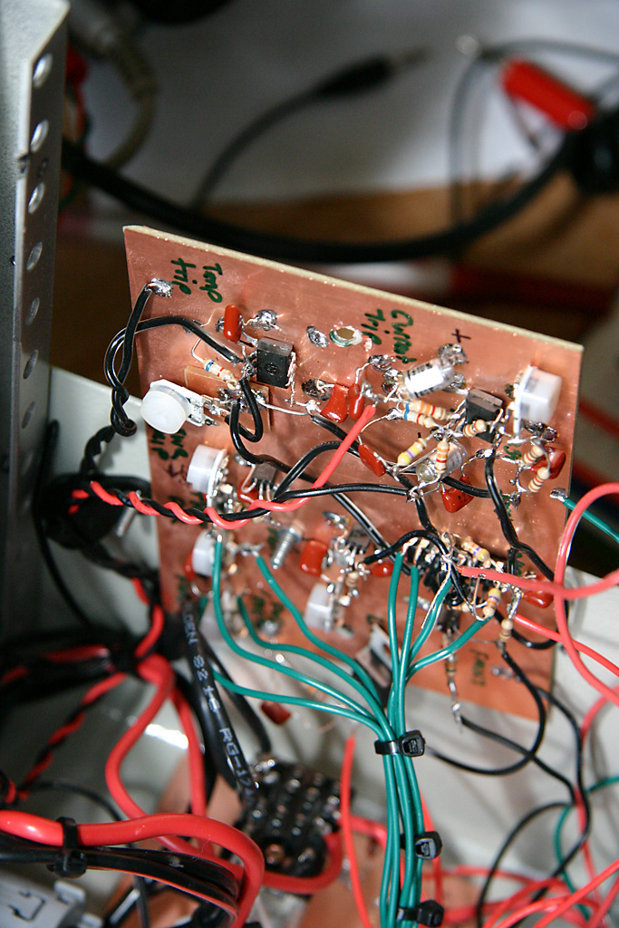
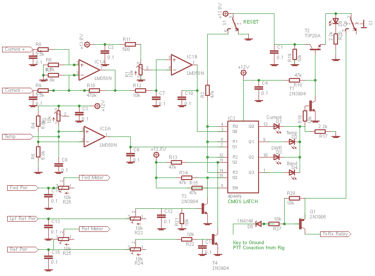
I had some time to work on the amplifier again this weekend. I built most of the control circuits, as described in Chapter 15 of the 2010 ARRL handbook, but I could not get them working. So I made quite a few modifications and ended up with the circuit shown below.
Note that my circuit is very different to the ARRL Handbook. I have reversed the inputs to the current sense comparator. I don't see how the circuit in the handbook can ever work. I have also increased the gain of the sense stage and removed 3.3k from each input. Finally I have reduced the resistor between the potentiometer and Vcc on the comparator input. I could not get the potentiometer into the right range of voltages otherwise.
For the temperature sensor I have used a much simpler circuit than the ARRL Handbook. In my circuit you set the potentiometer to the same resistance as the thermistor at the temperature that you want it to trip.
I tested the current sense using the 50 volt supply and some cheap 8ohm 20 watt resistors from Radio Shack. Current + joins to the positive end of a 0.01ohm Resistor (from Mouser.com) and Current - joins to the other end. I ran the following tests and measured the voltage at the output of IC1A, which is the input to the current sense comparator:
From this I calculate that the current trip needs to be set at 10.7625 volts for it to trip at 20 Amps. That is a very narrow range and I wish I had used a multi turn potentiometer to set the trip voltage. I tested some different trip voltages and the circuit worked, but it did not seem to trip at the exact voltage. There seems to be a small buffer before it trips.
To test the temperature sensor I again used the 8 ohm 20 watt resistors, but this time I used them as a heater. I attached a radio shack temperature probe to them together with the metal leg of the thermistor. It's important that the metal leg of the thermistor is in contact with the thing that is being measured. The glass body does not conduct heat well. This was easier to test than the current trip.
I decided that 50 to 60 degrees C would be a good conservative trip temperature for now. We will see if that works in practice later. The thermistor will be at about 2.1k at that temperature. I set it (you can measure the resistance or calculate the voltage that it should give when the thermistor is at room temperature). This tripped the op amp when the radio shack thermometer read 59 degrees C.
I built the SWR forward and reflected power control circuits, but I still need to build the actual sensor.
Postscript: The circuit on this page has been updated to show a supply voltage of 13.8V (or greater) which was needed when I tried to test the control board in situ.
Enter Comments Here:
| On: 09/20/15 9:09 Carlos said: |
| Nice work on your EB104 project. I am working on the same with mods to the EB104 board the main difference changes T3 to a transmission line transformer, and the K0GKD filter relay board. Do you have a parts list for the control board, I was planning on using the same ARRL board but if you ran into problems I want one that works. Thanks Carlos KE5DFK |
| On: 09/22/15 10:10 Chris AC2CZ said: |
| Carlos, thanks for the nice comments. I don't have a parts list. All I have is the circuit diagram on the page above. I think all of the component values are shown. If something is missing, then let me know and I can look it up in my notes. 73 Chris |
| On: 04/13/20 17:17 said: |
| On: 10/27/20 15:15 Stan, AJ4SN said: |
Hi, I used the same circuit as you for the overcurrent sense in my linear, but I sometimes have trouble with random tripping presumably due to rf. Did you have any problems like this? Stan aj4sn |
| On: 10/28/20 15:15 Chris G0KLA said: |
@Stan, I didn't have that issue. Make sure you have lots of decoupling capacitors perhaps? You should be able to keep the RF out of this circuit. |
Copyright 2001-2021 Chris Thompson
Send me an email