

Amplifiers are a favourite homebrew project. Years back I had helped build a couple of valve (tube in the US) amplifiers using a single 4CX250B on 2 meters. This produces a 250 Watt amplifier and has a strip line inductor to match the output. They never worked that well, but they were a lot of fun to build.
I wanted more power on HF so that I could make faster progress towards my homebrew DXCC. I wanted to try something different and modern so I setout to build a solid state linear based on the popular EB104 Motorola Engineering Bulletin by Helge Granberg. It uses 4 MRF150 FETs in push-pull parallel to acheive 600 Watts from about 6 Watts drive. That was a perfect design given my homebrew radio produces about 5 Watts barefoot.
In addition to these notes, you may want to read my blog posts which talk about the design and some of the difficulties getting this working:
I ordered the RF board and parts from Communication Concepts but if I was doing it again, I would use an RF deck from W6PQL. His boards are much higher quality and he is an engineer innovating in this space. Communication Concepts have simply repackaged the very old white papers from Motorola. They are dated designs and too be avoided, I now realize. Save yourself some headaches and give W6PQL some business.
With that said, the RF deck is not the hardest part to build, even if it is the most critical or performance. It turned out that I have to build the following components to create a working linear:

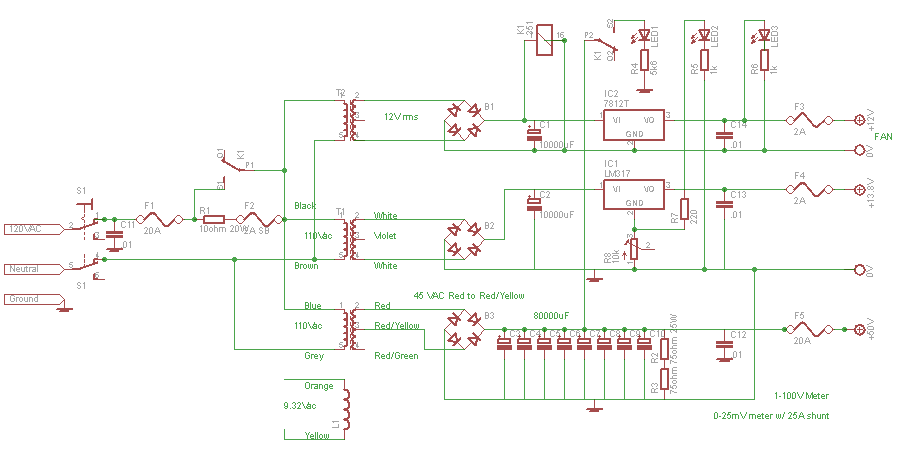
While time consuming to build, the power supply was the easiest component to construct and test. I designed it to produce 50 Volts at 25 Amps to supply the drains on the FETs and to supply the gate bias. I also included 13.8 Volts for control circuits and 12 Volts for the fan.
There is nothing complicated in the circuit. The 50V supply is not regulated other than by a bank of capacitors and by a bleeder resistor. I purchased 10000uF 80V capacitors from Mouser.com at a reasonable price. You can find capacitors on ebay too at good prices sometimes. The bleeder resistors run quite hot because they draw about a third of an amp, which is 17 Watts at 50 Volts. I used 25 watt power resistors and they seem to be fine. Keep them away from the electrolytic capacitors, which don't like to get hot.
 The only difficult component to obtain for the power supply is the transformer. Like others who have built the EB104 amplifier, I purchased the transformer from Ameritron, part number 406-1246. The color codes shown in the circuit diagram are for this transformer, but any high current 50 volt transformer will work.
The capacitor bank is capable of sourcing a lot of current at startup, so I use a relay to hold back the initial current. When the amplifier starts, there is a 10 ohm resistor that limits current into the transformer. Once sufficient voltage is established on the 12 volt circuit, it trips the relay which shorts out the 10 ohm resistor. This all happens in a fraction of a second.
The panel meters came from www.allelectronics.com, as did the 25 Amp shunt for ammeter. The shunt has not yet been mounted in the picture that shows the Power Supply open. It was mounted on the back panel at the top right. The case for the power supply and the amplifier are identical, a 8x12x9 inch Hammond steel enclosure with alumminim front and rear panels. They are part number 546-1401M from Mouser.com. It would probablly have been possible to fit all of the components into one enclosure, but I wanted to have the power supply seperate and under the desk. My receiver is a direct conversion design by KK7B. It has crystal clear audio, but is sensitive to transformer hum.
The Power Supply Circuit
By the time I purchased the transformer, the panel meters, the capacitors and a case from Mouser.com, it would have been much cheaper to by a second hand 48V switching PSU on ebay. That seems to be the route that others have taken, but then it would not be homemade... So I purchased the parts and built it myself.
Drilling the copper spreader was the hardest part of the project for me, but it need not have been. If I had known how to drill and tap copper in advance, then I would have had a lot less trouble. If I built this project again, then this would not be a difficult step.
I purchased the copper spreader from onlinemetals.com. They sell copper plate in small quantities. It's not cheap. I paid about $90 at the time for an 8"x6"x0.375" piece.
I purchased the heatsink that Communication Concepts sells. They call it the Model 99 and its just a bit larger than the copper spreader. I now recommend getting the copper and heatsink from W6PQL. He will tap the copper and mill the heatsink flat if you are not able to.
I'm usually very good at the mechanical aspects of my projects. I can cut holes in panels, mount switches etc. But I had not worked with copper before, and to be honest, I had not tapped a hole since I was in school about 25 years ago.
At first I broke two drill bits. They snapped off, lodged in the piece of copper for posterity. Advice on the internet suggested welding something to the broken piece to remove them. Well, that seems too hard. I marked out new holes 5mm to the side and started drilling the holes again. This time I used a can of bicycle lubricant (websites suggested WD40) and the holes cut much easier. I also drilled for a second, then removed the bit from the hole to clear debris, then drilled some more. After 5 or so one second cuts, I added another squirt of lubricant.
With drilling solved (or so I thought), I moved on to tapping, again using lubricant. Well, as you would expect, I broke a tap in one of the holes needed to mount a transistor. Its hard to describe how frustrated I was. I was very careful. I had put the tap in and out many times to clear debris. I used the lubricant. But it caught and snapped as I was removing it.
I could not remove the tap. I thought about moving the holes again, but with three pieces of debris stuck in the copper I ordered another piece. A $90 error. I thought about bolting the transistors in place, rather than tapping the holes, but that would be awkward and need countersunk holes. Something that is tricky to do accurately.
There is an easy solution to drilling and tapping copper though. Advice from the EMRFD Yahoo Group pointed me to the right lubricants to use. W4ZCB suggested Harveys thread cutting oil, and an 8 Oz bottle from Ace hardware was only $4.49. I ordered that and the holes were then easily drilled and relatively easily tapped. It turns out that copper is very sticky and other lubricants, while they work for a moment, can then bind and cause the tap to snap off.
The low pass filters need to cope with at least 600 Watts of RF. Just based on the simple formula Power = V^2 / R we can calculate the voltage for various loads. It will be the Root Mean Square (RMS) voltage, which is the typical value we refer to with alternating voltages, so we need to calculate the peak voltage, which is 1.414 times the RMS Voltage.
| Power Watts | Load Ohms | V rms | V Pk | Amps Pk |
| 1500 | 50 | 274 | 386 | 5.5 |
| 600 | 50 | 173 | 244 | 3.5 |
| 600 | 100 | 245 | 345 | 2.4 |
| 600 | 25 | 122 | 173 | 4.9 |
That tells us that there can easily be 350 volts across the capacitors in the filter. If we use RF capacitors, such as Silver Mica, then we should be fine. Non RF capacitors, such as ceramics, need to be derated at RF frequencies. Although Silver Mica capacitors seem very expensive, they are much cheaper than the transistors. If the capacitors fail then they can destroy the transistors at the same time.
I used ELSIE to design the Low Pass Filters. It comes free with the ARRL handbook and is easy to use. I did not design anything fancy, just 7 pole filters with a small amount of pass band ripple.
The filters are switched with Tyco 8 amp 250 volt relays. I have one at each end of a filter, with both poles connected in parallel to increase the current that they can handle. A switch on the front panel simply routes 12 volts to the needed set of relays. Each line going to the relays is connected to a front panel led which shows which band has been selected.
If that all sounds a bit too hard then you can order a W6PQL filter board online, complete with relays.
To prevent a disaster when the wrong band is selected, an SWR sense circuit can be placed between the amplifier and the low pass filter. If the wrong band is selected then this circuit will take the amplifier offline. See the control circuits below for details.
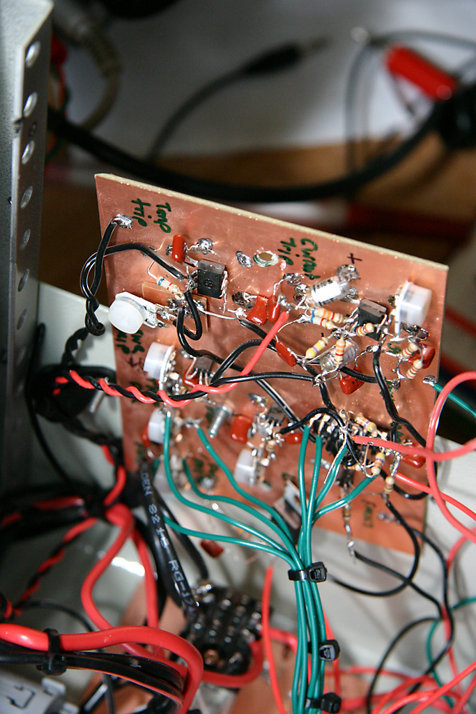 This circuit is based on the control circuit shown in the 2010 ARRL Handbook, although I made a number of modifications to fit with this design. The control board connects to several sensors.
All of the sensors connect to a CMOS latch, and all of them trigger the same result. The amplifier is taken offline and an LED is lit to explain why. The reset switch is then clicked on and off to bring the amplifier back online again.
High Current: The current sense circuit uses a very small resistor, 0.001 ohms. At 20 Amps, 2mV is dropped across the resistor. The small voltage drop is amplified by an Op Amp and then a second Op Amp is configured as a comparator. The variable resistor R1 is then used to set the current trip level. I used 20W wirewound resistors from Radio shack as a test load to setup the current trip.
High Temperature: The temperature sensor is simpler. The 10k thermistor connects directly to a comparator.
The Control Circuits
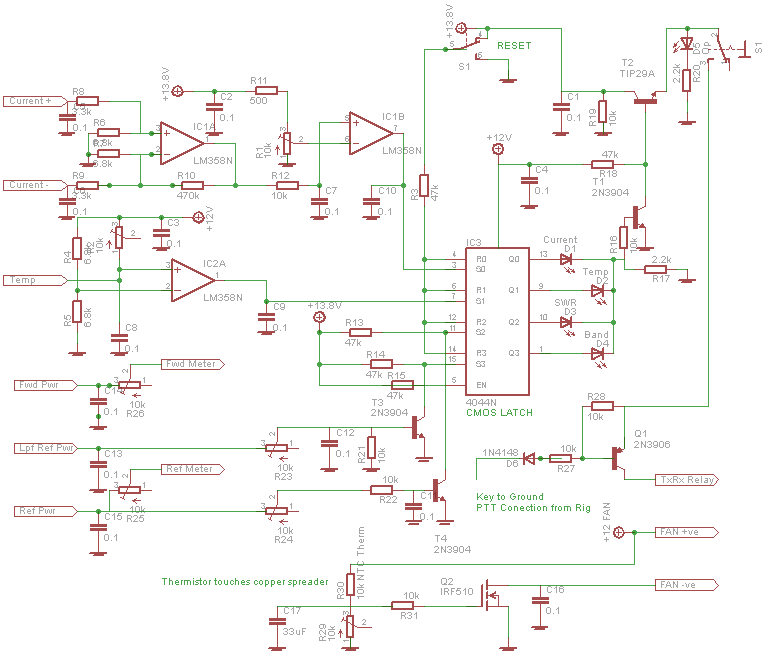
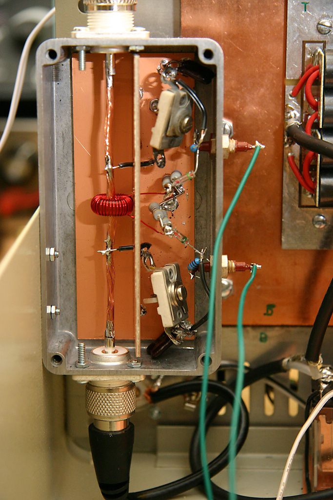 High SWR:Perhaps most importantly I wanted to detect reflected power and take the amplifier offline. Ideally the amplifier should survive no antenna, a shorted antenna, high SWR due to snow/ice and any other combination. I could not get the SWR sensor in the ARRL design to work, so I decided to build a classic forward and reflected power meter circuit. This meant I could have forward and reflected power meters on the front of the amplifier.
No one seems to publish these circuits anymore, so I went to the December 1969 QST Article "In line RF power metering" by Doug DeMaw W1FB (membership of the ARRL required to view the archives). There is also another useful Doug DeMaw article in the December 1983 QST "A beginners look at RF Power Measurement". I modified the circuit slightly and built it in a diecast box, using a piece of printed circuit board as the shield between the torroid sensor and the measurement circuit.
LPF Reflected Power: The last sensor will measure the reflected power from the low pass filters. This will determine if the wrong LPF has been selected. I have not built this sensor though I have mounted the LED and built all of the associated control circuits. I will build this out when I construct the rest of the low pass filters.
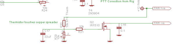
The circuit is pretty straight forward (ignore the components along the top because this is cut from a larger circuit diagram). The thermistor is in physical (but not electrical) contact with the copper spreader. When it heats up slightly and its resistance lowers, the voltage on the FET gate rises above 4V and the FET is switched on. At first the fan runs slowly, as the temperature rises. At room temperature, the variable resistor is set so that the fan is just off and the voltage on the FET gate is probably 3-3.5V.

I can highly recommend building this amplifier. It was a struggle at times, but it has been very satisfying to use.
73, Chris
Copyright 2001-2021 Chris Thompson
Send me an email